Pressure locked steel grating is a high strength grating made by pressing the cross-bar into the bearing flat steel or the pre-grooved bearing bar at each intersection to form the panels. Featuring light structure, high-performance, low-maintenance, Pressure locked bar grating is used in civilian and commercial buildings, theatres, subway, suburban railway and other municipal engineering, for facade cladding, screen and pedestrian walkways.
Pressure Locked Grating Types:Heavy type and light dovetail type. Dovetail pressure locked type grating is made by deforming the cross bar into dovetail slot in the bearing bar by way of hydraulic pressure.
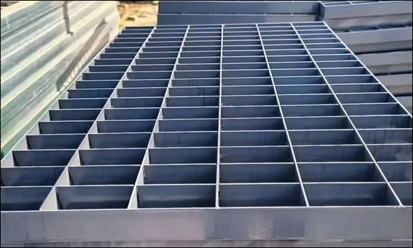
Common material types include Aluminum, Carbon Steel, Powder Coated Carbon Steel, Galvanized Steel and Stainless Steel. Popularly used materials include mild carbon steel and stainless steel.
Manufacturing Process:
Compared with Welded Steel Grating: Pressure locked grating has lower durability compared to welded grating due to the lack of a permanent bond like welding, but still provides sufficient strength for many applications. Press locked steel grating is mainly used for light to medium load applications, welded gratings are used for heavy loading applications.
Compared with Riveted grating: Riveted grating provides a very strong connection that can handle higher loads and more rigorous use than pressure locked gratings.
Serrated pressure locked bar grating has an anti slippery extra safety surface. Spacing range can be custom designed to meet the requirements. This method of manufacture is particularly flexible that it allows for the production of grating with custom bearing bar spacing.
Specify the following requirements when order:
Height of End Plate (H);
Pitch of Cross Bar (CP);
Width of Grating (W);
Length of Grating (L);
Thickness of Bearing Bar (T);
Pitch of Bar (PB);
Height of Bearing Bar (H).
1. All bearing bars, Cross bars & frame angles conform to the requirements of ASTM 36.
2. Gratings are manufactured by pressure locked, rectangular steel design. Main bars 2¼" x3/16", Spaced 15/16" center to center, cross bars 1"x 1/8" rectangular cross section, Flush top and spaced 2" center to center.
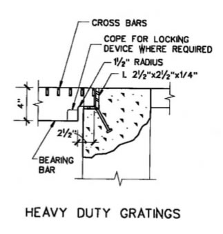
3. At locations where heavy duty gratings are used: 4" x -3/8" main bars. Spaced 11/8"' center to center. Cross bars of 1" x 3/8" rectangular cross section. Flush top and spaced 4" center to center.
4. Gratings and frame angles hot dipped galvanized after fabrication.
5. Installing frame angles and gratings to match the top of the sidewalk to eliminate tripping hazards.
6. Size of the bearing bars, cross bars, frame angles & studs for removable and fixed gratings are the same.
7. One set of removable gratings provided for each series of ventilators at locations indicated or as directed by the engineer.
8. Cuts for four or more bearing bars. Not bearing directly on supporting steel shall be provided with a stress band of the same size as the beared bar. Notching of bearing bars at the supports to maintain elevations will not be permitted unless approved by the engineer.
9. Gratings designed for h20 wheel loads.
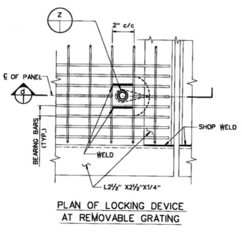
Heavy duty sidewalk ventilation grating
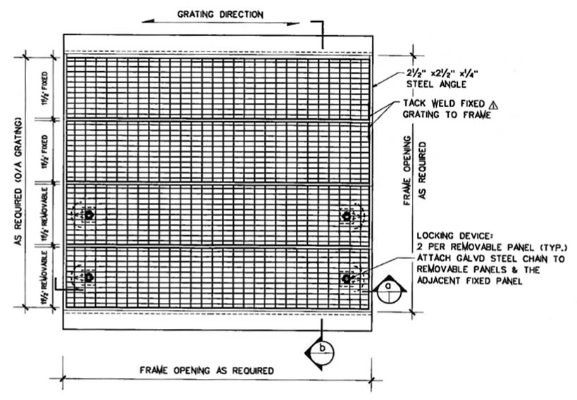
2-1/2" x 2-1/2" x 1/4" angle iron frame
4" x 3/8" bearing bars 1-3/8" center to center
1"-
1/2" x 1/4" rectangular cross section
Connection: (4) tack welds to affix panel to each
supporting angle
Flush top and spaced 4" center to center.
With locking devices.
Components hot dip galvanized per astm 123 standard.
Heavy duty sidewalk ventilation grating, with no locking device
Radius grating panel
2-1/2" x 2-1/2" x 1/4" angle iron frame
4" x 3/8" bearing bars 1-3/8" center to center
1"-
1/2" x 1/4" rectangular cross section
Connection: (4) tack welds to affix panel to each supporting angle
Flush top and spaced 4" center to center.
No locking devices.
Components hot dip galvanized per astm 123 standard.
Light Duty Dove Tail Steel Bar Grating for Pedestrian Traffic - Pedestrian Grating
Light Duty Dove Tail Steel Grating
Grating Panels: 2 feet wide x 24 feet long.
Bearing bar depth: 3/4" to 2 1/2"
Bearing bar
thickness: 3/16”
Surface: Smooth, serrated.
Finishes: Steel, hot dip galvanized, black bitumen painted.
Application: Light Duty Dove Tail Steel Grating is mainly used in platform stair treads and pedestrian walkways.
1. General Techincal Information for Platform Stair and Floor Grating
General notes for common construction of platform structure with pressure locked bar gratings.
Reference used in conjunction with applicable civil, structural,
architectural, piping & electrical design drawings of each specific projects.
Design and construction of steel structures shall be in accordance with the following
project specifications and eurocodes.
- P0058lng-0028-db-0001 : Structural design basis
- En 1990 eurocode : Basis of structural design
- En 1991 eurocode : Actions on structures
- En 1992 eurocode : Design of concrete structures
- En 1993 eurocode : Design of steel structures
- En 1998 eurocode : Design of earth
- Dep 34.28.00.31 : Steel structures
- Dep—34.00.01.30—p4049nrp—00—pv : Structural design and engineering
- Dep-34.1 1.00.1 2-p4049nrp-00-pv : Geotechnical and foundation engineering-onshore
- Dep-34.1 3.20.31-p4049nrp-00-pv : Roads, paving, surfacing. Slope protection and fencing
- Dep-34,13,20.31-p4054lng-00-pv : Roads, paving, surfacing. Slope protection and fencing
- Dep-34.19.20.11-p4049nrp-00-pv : Passive fire protection for onshore facilities
- Dep-34.14.2 0.31-p40 49nrp-00-pv : Drainage systems and primary treatment facilities
2. Structural steel
A) En 1993 eurocode shall be used for design of structural steel.
B) All structural shapes. Plates. Angles. Channels and bars shall be in accordance with astm a36/a36m or en 10025 s275jr.
C) Pipe shall conform to astm a53/a53m type e or s. Grade b or astm al06 grade b.
D) Structural tubing shall conform to astm a501 or astm a500 grade b.
E) All gusset and stiffener plates shall not be thinner than the members to be connected, and shall have a thickness of at least 10mm.
3, Connection
A) Connections shall be in accordance with standard connection details unless otherwise
shown on design drawings.
B) Shop connections May be bolted or welded. Field connections shall normally be bolted however when approved by company, welded field connections May be used.
C) Single bolt connections will not be permitted.
D) Connections shall be designed as bearing type connection.
E) All bolted connections shall be provided with washers and nuts
F) All bolted connections exposed to dynamic loads and vibrations
(Supporting e.G. Machinery, crane beams, flare stacks, masts, etc.)
Shall be provided with lock nuts.
4. Welding
A) All welding and welding procedures shall be in accordance with ansi/aws d1.1 or contractor approved equivalent.
B) Inspectors shall be qualified and certified as ansi/aws or contractor approved certified welding inspectors.
C) Run-off bars and extension tabs shall be removed before corrosion protection coatings are applied or before being sent to the field for erection.
D) Field welding shall be minimized and all weld shall be smooth and continuous.
E) Location, size, length or other characteristics of the welded joints shall be clearly shown in the design drawings.
F) Butt welds will be complete penetration butt welds made between fusion faces, and the end of the welds will have full throat thickness.
5. Platform & walkway
A) Minimum width of platform shall be 1000mm and walkway shall have a minimum width of 750mm.
B) Minimum headroom for platform and walkway shall be 2300mm.
C) Minimum width of walkways over ground level pipe tracks shall be 600mm.
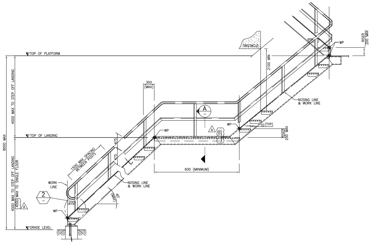
6. Stairway
A) All stair shall be in accordance with standard drawings.
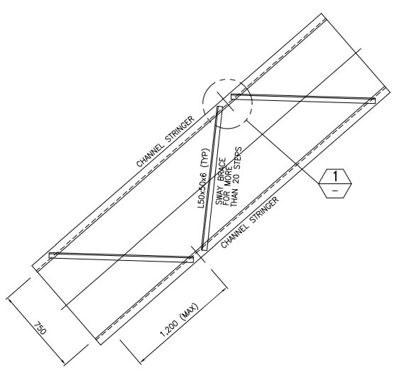
B) Stairways shall be constructed of standard channel stringers with open grating treads. Grating treads shall be 25mm thickness.
C) For one single stair, maximum height between grade level and top of floor is 4000mm.
D) For multiple stairs with intermediate platform, maximum height between landings shall not exceed 4000mm.
E) Slope of stairway, ratio of riser and tread, is 5 in 6.
F) Minimum width of stair landings shall be 750mm.
G) Minimum headroom for stairway shall be 2100mm.
H) Stair treads shall be made of hot-dip galvanized grating in accordance with iso 1461.
7. Ladders
A) All ladders shall be in accordance with standard drawings.
B) Single-stage ladders shall be no longer than 9000mm. Multiple-stage ladders shall be staggered at least every 6000mm.
C) Ladders shall be made with side steps normally.
D) Ladders May be installed instead of staircases if the ladders are only required for occasional use and escape routes.
8. Handrailing
A) All handrails shall be in accordance with standard drawings.
B) Minimum clearance between handrail or top rail of stair railing/standard railing and any obstruction shall be 75mm.
9. Grating and stair tread
A) Grating and stair tread shall be fabricated and installed in accordance with standard drawing. And shall be hot dip galvanized including fixed material in accordance with iso 1461.
B) Top surface of bearing bars shall be plain unless serrated is specified.
C) Grating stair treads shall have abrasive or checkered plate nosing.
D) Location and limits of grating and direction of span of grating bearing bars shall be in accordance with design drawings.
E) At joints in grating floor system, cross sections of bearing bars for grating panels shall be aligned with cross sections of abuning panels to maintain spacing symmetry. Grating joints shall be permitted only at supports.
F) When removable grating is shown on design drawings, each removable fabricated grating shall not exceed 160kg.
G) Each grating panel to be fixed to floor beams by means of at least 4 clamps (In case of very large panels minimum 4 clamps/m2).
10. Checkered floor plate
A) Checkered floor plate shall conform to astm a786/a786m pattern 5.
B) Checkered floor plate shall be hot dip galvanized in accordance with iso 1461.
C) Checkered floor plate shall be four-way, raised pattern steel plate with a thickness of 6mm.
D) Checkered floor plate shall be attached to supports of steelwork with 12mm diameter countersunk bolts, unless otherwise noted.
E) A 13mm diameter drainage hole shall be provided per square meter of floor plate.
11. Coating
| AREA | ITEM | APPLIED STRUCTURE | APPLICATION SPEC. | PAINTING SYSTEM CODE | SURFACE PREPARATION | TOTAL OFT MICRONS | PRIMER COAT | INTERM. COAT | FINISH COAT | COLOR/RAL CODE |
| TOPSIDE | STRUCTURAL STEEL AND PLATE (WITHOUT FIREPROOFED) | ALL STRUCTURES EXCEPT JETTY IMPOUNDING BASIN |
P4054LNG.10.10.19.009 (ATMOSPHERIC ZONE) | PC2-N | Sa 2.5 / SP10-82 | 300 µ | ZINC RICH PRIMER (60p) | EPOXY MIDCOAT (2x95 µ) | POLYURETHANE (50 µ) | LIGHT GRAY RAL 7035 |
| STRUCTURAL STEEL AND PLATE (WITH FIREPROOFED) | 30.48.00.31 -P4054LNG-PV | NO.2 | SSPC-SP 10 OR A,8,C,D Sa 2½ OR NACE 2 |
150 µ | INORGANIC ZINC PRIMER (50µ) | - | POLYAMIDE EPOXY (100µ) | N/A | ||
| HANDRAIL. LADDER | P4054LNG.10.10.19.009 (ATMOSPHERIC ZONE) |
l.HOT DIP GALVANIZED AS PER ISO 1461 2. F02-N | - | 200 µ | EPOXY PRIMER (150µ) | - | POLYURETHANE (50µ) | YELLOW, COLZA RAL 1021 | ||
| GRATING, CHECKERED PLATE | HOT DIP GALVANIZED AS PER ISO 1461 (NOT PAINTED) | - | - | - | - | - | N/A | |||
| ONSHORE & OFFSITE |
STRUCTURAL STEEL AND PLATE (WITHOUT FIREPROOFED) |
-EQUIPMENT STRUCTURE -LOCAL SUPPORT -ACCESS PLATFORM
|
30.48.00.31 -P4054LNG-PV | NO.3 | SSPC-SP 10 OR A,8,C,D Sa 2½ OR NACE 2 |
225 µ | INORGANIC ZINC PRIMER (50 µ) |
POLYAMIDE EPOXY (100 µ) | POLYURETHANE (75 µ) | LIGHT GRAY RAL 7035 |
| STRUCTURAL STEEL AND PLATE (WITH FIREPROOFED) | NO 2 | 150 µ | INORGANIC ZINC PRIMER (50 µ) | - | POLYAMIDE EPOXY (100 µ) | N/A | ||||
| STRUCTURAL STEEL AND PLATE (INSIDE SEAWATER INTAKE PIT) |
|
P4054LNG.10.10.19.009 (WETTED AND INTERMITTENTLY -WETTED ZONE) | FC1-N | Sa 2.5 / SP10-82 | 500 µ | ZINC RICH PRIMER (60 µ) | HIGH SOLID EPOXY (220 µ) | HIGH SOLID EPOXY (220 µ) | LIGHT GRAY RAL 7035 | |
| HANDRAIL. LADDER |
|
P4054LNG.10.10.19.009 (WETTED AND INTERMITTENTLY -WETTED ZONE) |
FC1-N | Sa 2.5 / SP10-82 | 500 µ | ZINC RICH PRIMER (60 µ) | HIGH SOLID EPOXY (220 µ) | HIGH SOLID EPOXY (220 µ) | YELLOW, COLZA RAL 1021 | |
| ALL ITEMS EXCEPT MENTIONED ABOVE | 30.48.00.31 -P4054LNG-PV | NO.3 | SSPC-SP 10 OR A,B,C,D Sa 2½ OR NACE 2 |
225 µ | INORGANIC ZINC PRIMER (50 µ) | POLYAMIDE EPOXY (100 µ) | POLYURETHANE (75 µ) | YELLOW, COLZA RAL 1021 |
||
| GRATING, CHECKERED PLATE | SEAWATER INTAKE PIT ONLY | P4054LNG.10.10.19.009 | HOT DIP GALVANIZED AS PER ISO 1461 (NOT PAINTED) | - | - | - | - | - | N/A | |
| EXCEPT SEAWATER INTAKE PIT | 30.48.00.31 -P4054LNG-PV | - | - | - | - | - | N/A | |||
| ALL | FASTENERS SUCH AS BOLTS, NUTS AND WASHERS | STEEL STRUCTURE -PIPE RACK -EQUIPMENT STRUCTURE -LOCAL SUPPORT -ACCESS PLATFORM |
30.48.00.31-P4054LNG-PV | HOT DIP GALVANIZED AS PER ISO 10684(N0T PAINTED) | - | - | - | - | - | N/A |
| ANCHOR BOLTS | 30.48.00.31 -P4054LNG-PV | HOT DIP GALVANIZED AS PER ISO 1461 (NOT PAINTED) | - | - | - | - | - | N/A |
12. Fabrication and Erection
A) Fabrication and erection shall be in accordance with design.
B) Erection tolerances shall be in accordance with eurocode specification.
C) Structural steel elements shall be plumb, level aligned and within tolerances.
D) Shop splices, substitutions of member sizes or changes in details or dimensions shall not be permitted without written authorization from engineer.
E) All pieces shall be clearly marked with a permanent identifying erection mark number.
F) Before surface preparation, fabricator shall remove all sharp corners, burrs, weld spatter. Slag. Weld flux. Loose mill scale and other foreign maher.
G) Platforms, stairways and handrails shall be shop-assembled in the largest units suitable for handling and shipping. Ladder cages shall be shop-assembled on ladders.
H) Method of fastening grating shall be shown on design drawings. A minimum of two fasteners per panel shall be used at each support with a minimum of four fasteners per panel. Fabricator shall supply the fasteners including 5% extra to cover losses.
I) Joints perpendicular to span of grating and checkered floor plate shall occur only over support members.
J) Column splices having gaps of 2 mm to 6mm with less than 70 percent contact between bearing surfaces shall be packed with non-tapereo steel shims. Gaps greater than 6mm are not acceptable.
K) Connections requiring new holes in existing steel shall be drilled or punched. Bolt hole diameters shall be 2mm greater than nominal diameter of bolts or as specified on design drawings. Damaged painted or galvanized surfaces shall be repaired.
13. Fireproofing
A) Fireproofing shall be performed with fendolite
B) Fireproofing material shall satisfy 90 minutes fire resistance time based on ul 1709. The critical temperature shall be 400°c to maintain 100% of mechanical strength. Fireproofing shall be applied in accordance with fireproofing zone drawing, which are prepared considering pool fire & jet fire in accordance with ora study report.
C) Minimum warranty period shall be five years.
D) Mesh reinforcement for fireproofing shall be in accordance with p0058lng-00-19-1-c0039.
E) Material and extent of fire proofing shall be indicated / distinguished in design drawings.
14. Execution class
Steel execution class shall be defined in accordance with en 1090-2, as below:
| Area | Steel Structure | Execution Class |
| Overall | Local Access Platform | EXC 2 |
| Local Pipe Support | ||
| Jetty / Trestle | JETTY /TRESTLE PIPERACK FLARE K.O. DRUM PIPERACK FLARE PIPERACK LOADING ARE STRUCTURE (*) |
|
| Tank | FLARE PIPERACK OVERBRIDGE STRUCTURE(*) TANK PIPE RACK (*) STRVCTURE - I |
|
| Process | Main Piperack (*) 30-PR-001 & 002 40-PR-001 ORV OPERATING PLATFORM ORV SUB RACK SCV OPERATING PLATFORM RECONDENSER STRUCTURE (*) |
|
| Utility | Sub Pipe Rack | |
| Offite (BE-180) | Steel Modification Work |
(*) Note: For 1st steel beam to support esd valves, steel execution class 3 shall be applied. Steel beam for exc 3 shall be marked on steel design drawings. It shall be considered by quality control as per EN 1090-2.
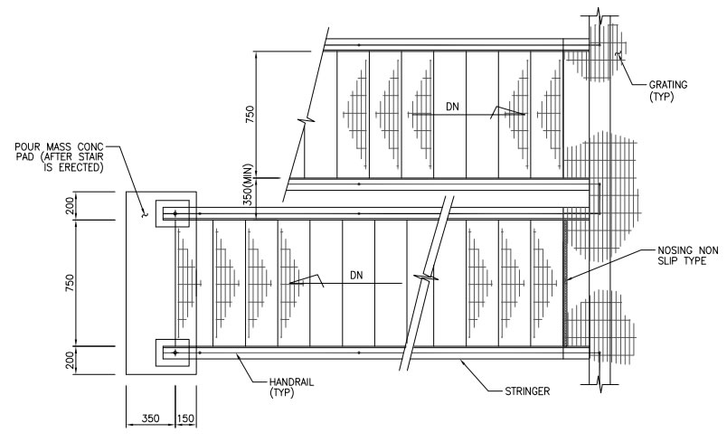
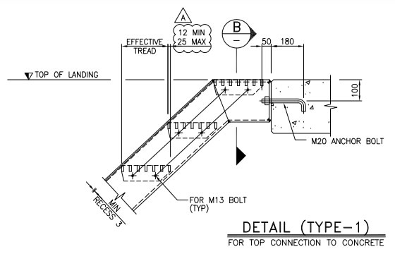
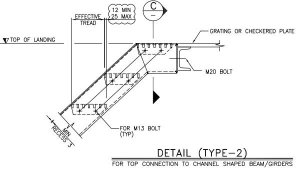
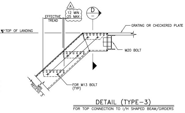
Platform (Channel, Stair, Structural Work) Plan:
Stair Tread Details:
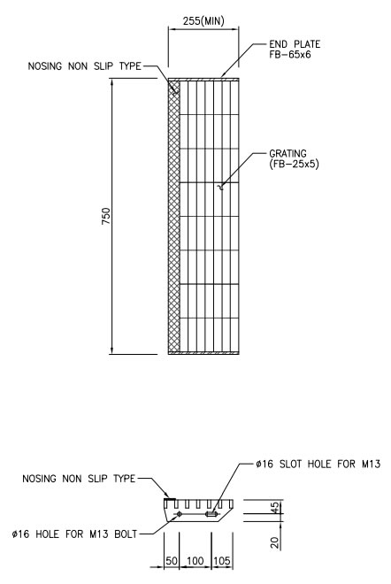
Stair tread grating: FB 25x5
End plate: FB 55x6
Nosing: Non slip checkered plate
Grating Panels and Floor Plate Fastening

Floor plate connected with beam / channels

Grating fastened with saddle-clip anchors
GRATING & FLOOR OPENING DETAILS
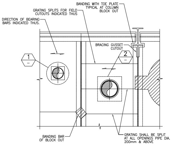
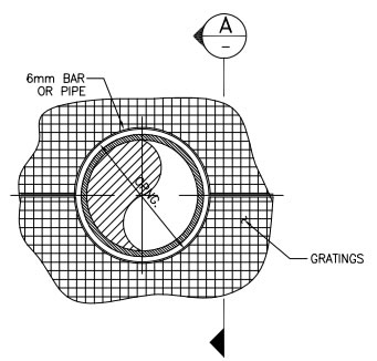
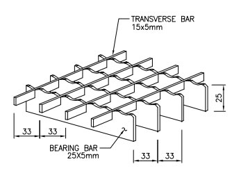
Press locked grating panels detail:
Bearing bar:25x5mm, pitch 33, traverse bar 15x5mm
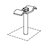
Saddle clip, stud or threaded stud M8 and nut
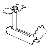
Saddle clip, 8mm diameter BOLT and Nut, and bottom kicker
Type of grating: Serrated flat bars type
Maximum span: 1200mm
Grating Finish: Hot dip galvanized
Material standard: ASTM A123/A123M and ASTM A143/A143M or ISO 1461
Grating Fastening
Fixing: Each grating panel to be fixed to floor beams by 4 clamps. Min. 4 clamp per square meter for very large pannels.
Positioners be fieldwelded immediately upon placement of grating and protective zinc layer reconditioned.
Positioners at each order of grating panel except at edge of platform where toe plate exists.
Cut outs trimmed with a binding bar, or with toe plate. Binding bars and toe-plate secured to every loadbearing bar.
Samples Illustration:
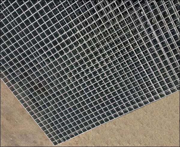
Press Lock Grating - 25X5 -Load Bar, 15X5- Cross Bar ,30X30 - Pitch (PRESS LOCKED NOT WELDED)
Qindelin Steel Grating Engineering Corporation
Add: New Development Zone, Dezhou, Shandong, China
URL: https://www.steelgrating.org
Email: sale@steelgrating.org
